 |
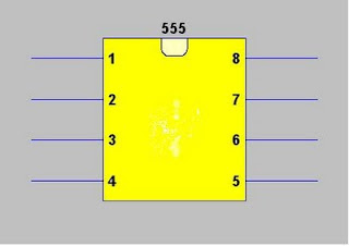
| 555 timer |
555 timer is an integrated circuit that is use primarily for pulse generation and timing circuitry. This ic can be operated in monostable mode, astable mode, or bistable mode operation. This IC consists of two voltage comparators, a bi-stable flip flop, a discharge transistor, and three 5k resistor divider network. This timer ic is capable of producing time delays using only the value of external resistor and capacitor combination.
 |
| 555 timer internal connection |
Pin 2: Trigger Terminal. This pin is an inverting input to a comparator that signal voltage feed is much lesser in magnitude compared to the 1/3 value of the supplied voltage causes to activate flip-flop from set to reset.
Pin 3: Output Terminal. The output voltage approximately equal to the supplied voltage in pin 8. this pin is used to drive or trigger loads like transistors or mosfets.
Pin 4: Reset Terminal. Negative signal is used to drive the ic into reset .usually this pin is shorted to pin8 to avoid false triggering when the IC is not intended for reset purposes
Pin 5: Control Voltage Terminal. Serves as control voltage for 555 ic. A capacitor is connected this pin to ground for supplied voltage filtering purposes.
Pin 6: Threshold Terminal. This is the non-inverting input terminal of comparator 1, which compares the voltage applied to the terminal with a reference voltage of 2/3 of the supplied voltage. The amplitude of voltage applied to this terminal is responsible for the set state of flip-flop.
Pin 7 : Discharge Terminal. This pin is connected internally to the collector of transistor and mostly a capacitor is connected between this terminal and ground. It is called discharge terminal because when transistor saturates, capacitor discharges through the transistor. When the transistor is cut-off, the capacitor charges at a rate determined by the external resistor and capacitor.
Pin 8: Supply Terminal. A supply voltage is connected in this terminal.
555 timer basic operation
Comporator 1 has a referrence voltage equal to 2/3 of the supply voltage. This is set by the voltage divider configuration of three 5k resistors. When the voltage at the threshold,pin6, is much greater than the control voltage at pin5, then the output of the comparator is high thus set the flip-flop, and in return enabling the discharge transistor to saturates and discharge the capacitor externally connected at pin7.in this particular case, the output of pin3 is low. To change the output of flip-flop to low and the output to pin 3 to high, the voltage at the trigger input must fall below 1/3 of the supplied voltage. a voltage must be applied to pin 5 but if not in use, a capacitor is usually connected from this pin to ground to filter noise from environment or source that may lead to false triggering. Usually pin4 is shorted to pin8 when the reset is not used.
555 timer operation
The 555 timer ic can operate in either monostable or astable mode, or bistable mode.
 |
| monostable configuration |
 |
| monostable out |
The duration time t, which is the time it takes to charge C to 2/3 of the supply voltage, is given by
t=RCln(3)
In astable mode, the 555 timer a rectangular pulses having a specified frequency, and specified time for high and low output. A resistor R1 that is connected between pin8 and pin7, resistor R2 connected between pin7 and shorted pin6 and pin2, and a capacitor C connected across the shorted pin6 and pin2 and ground, sets the 555 timer frequency and Thigh and Tlow duration.
 |
| astable configuration |
 |
| astable output |
f=1/[(ln(2)(C)(R1+2R2)]
The high time from each pulse is given by
Ton=ln2(C)(R1+R2)
and the low time from each pulse is given by
Toff=ln2(C)(R2)
where R1 and R2 are the values of the resistors in ohms and C is the value of the capacitor in farads.
See 555 timer calculator to check this formulas using different values of R1,R2, and C
your efforts are worth appreciating
ReplyDeletethanks!
ReplyDeleteI like it.
ReplyDelete